


CHARON-AXP for Windows configuration
- Copy Page Tree
- Bruno Miretti (Deactivated)
- Kirill Nikolaev (Unlicensed)
Table of Contents
Creation of CHARON VM configuration
When a CHARON Virtual Machine (VM) is created from a template using the CHARON Virtual Machines Manager, it has to be updated to meet the desired configuration.
This configuration is represented as a text file ("configuration file") containing some specific keywords to define the main settings such as amount of memory, number of CPUs, peripheral devices as well as specifics of CHARON VM executions such as name of VM log file, number of host CPUs used for emulation, etc.
To change the configuration file, open the CHARON Virtual Machines Manager from its shortcut on Desktop / Start menu or from the tray menu item, select the target CHARON VM and press the "Edit Configuration" button:
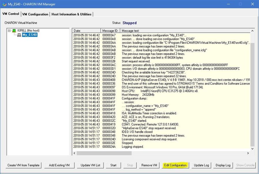
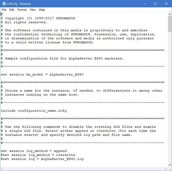
Notepad will be used to edit the configuration file:
HP Alpha model specification
The first configuration statement is the specification of the exact HP Alpha hardware model to emulate, for example:
|
You must leave this line untouched.
![]() If you create the CHARON VM configuration file from scratch, it must be the very first uncommented line in the configuration file.
If you create the CHARON VM configuration file from scratch, it must be the very first uncommented line in the configuration file.
Configuration name
The next configuration statement is the "Configuration name" option. If the virtual machine has been created using an existing template, the configuration name is defined in the configuration_name.icfg file otherwise it is defined directly in the configuration file using the "set session configuration_name = <...>" syntax:
include configuration_name.icfg |
Notes:
- The configuration name is reported in the log file and is used to set the log file name for rotating log (see explanations further).
- Changing the configuration name in the "configuration_name.icfg" file does not change the name of the virtual machine at Virtual Machines Manager level.
- The "configuration_name.icfg" file can be found in the home directiory of the VM. Select the target VM, open "VM Configuration" tab and press "Explore" button.
The configuration name can be any label that is meaningful.
Example:
set session configuration_name = My_ES40 |
It is possible to specify a configuration name containing spaces, in this case use quotation marks:
set session configuration_name = "My ES40" |
Log file parameters
The execution of a CHARON VM creates one log file or a set of log files reflecting the progress of its start-up and ongoing operations: start and end time of execution, system information, license and configuration details, warnings, reports on problems that may occur, etc. In case of problems with either the running CHARON VM or the emulated system configuration (such as the absence or malfunction of certain devices), the log file is the primary source to be analyzed for troubleshooting.
![]() If it becomes necessary to contact Stromasys for support, the configuration and log files, plus the license number, will be requested to begin the problem resolution.
If it becomes necessary to contact Stromasys for support, the configuration and log files, plus the license number, will be requested to begin the problem resolution.
Here is an example of a CHARON VM log file:
|
The next group of parameters defines the name of the CHARON VM log file and how the CHARON VM will use it:
|
Rotating log (default)
By default the CHARON VM utilizes a so-called "rotating log" method. This means that a new default log file is always created each time the CHARON VM starts and if the size of the log file exceeds 64Kb (previous log files are kept).
This mode is turned on if all the log parameters above are disabled (commented out) or the "session_log" parameter is pointing to a directory rather than to a file. If a directory is specified, the log files will be created in that directory.
The names of the rotating log files are composed as follows:
|
If the "Configuration name" parameter described before is omitted (commented out), the log name has the following format instead:
|
Note that "xxxxxxxxx" is an increasing decimal number starting from "000000000" to separate log files with the same time of creation.
![]() The "log" parameter, if specified, must correspond to an existing folder.
The "log" parameter, if specified, must correspond to an existing folder.
![]() If the path is not specified, the log file is created in the "Home directory" mentioned in the VM Configuration tab of the CHARON Virtual Machine Manager.
If the path is not specified, the log file is created in the "Home directory" mentioned in the VM Configuration tab of the CHARON Virtual Machine Manager.
Single log
Alternatively it is possible to use a single log file. Uncomment the "set session log" line and specify the desired log file name. Optionally, a path can be added to the log file name.
![]() If the path is not specified, the log file is created in the "Home directory" mentioned in the VM Configuration tab of the CHARON Virtual Machine Manager.
If the path is not specified, the log file is created in the "Home directory" mentioned in the VM Configuration tab of the CHARON Virtual Machine Manager.
The log file can be extended specifying "log_method = append" (*recommended for reporting issues*) or overwritten, specifying "log_method = overwrite".
Below is a specification of a CHARON VM log file located in the "C:\CHARON logs" directory which will be appended each time the CHARON VM starts:
|
CPU affinity
This setting binds the running CHARON VM CPUs to particular host CPUs.This should be used for soft partitioning host CPU resources or for isolating multiple CHARON VMs on the same host from each other. By default the emulator instance allocates as many host CPUs as possible.
“Affinity” overrides the default and allows explicit specification of which host CPUs will be used by the instance. Affinity does not reserve the CPU for exclusive use.
|
The example above directs CHARON VM to use CPU 0,1,2 and 3.
If this parameter is omitted CHARON host will allocate available CPUs automatically.
![]() Note that the number of the specified host CPUs must correspond to the number of the emulated CPUs (one host CPU for one emulated CPU; this value is specific for each HP Alpha model) and number of CPUs needed for CHARON application itself ("n_of_io_cpus").
Note that the number of the specified host CPUs must correspond to the number of the emulated CPUs (one host CPU for one emulated CPU; this value is specific for each HP Alpha model) and number of CPUs needed for CHARON application itself ("n_of_io_cpus").
Number of host CPUs dedicated to CHARON I/O
This setting reserves host CPUs (of those specified by “affinity” parameter, if any) for use by CHARON VM for I/O handling. By default CHARON VM reserves one third of available host CPUs for I/O processing (round down, at least one).
The “n_of_io_cpus” overrides the default by specifying the number of I/O host CPUs explicitly
Example:
|
The example above directs CHARON VM to use 2 CPUs for CHARON I/O operations.
![]() Note that the number of the specified CPUs dedicated to CHARON VM I/O operations must correspond to the total number of available for CHARON CPUs (restricted by "affinity" parameter if needed) and the number of the virtual HP Alpha CPUs to be emulated.
Note that the number of the specified CPUs dedicated to CHARON VM I/O operations must correspond to the total number of available for CHARON CPUs (restricted by "affinity" parameter if needed) and the number of the virtual HP Alpha CPUs to be emulated.
Setting a specific HP Alpha model
CHARON-AXP allows to specify an exact model of HP Alpha.
For example for HP AlphaServer ES40 family the template configuration file contains the following options:
#============================================================================ #set ace cpu_architecture = EV6 #============================================================================ set ace cpu_architecture = EV67 |
Just uncomment the provided lines to apply a certain model (It is "AlphaServer ES40 6/667" in the example above).
The full description of the parameters and other models that can be also configured is available in the "Configuration details" chapter of this User's Guide.
Reducing number of emulated CPUs
If the CHARON host does not contain enough CPUs to emulate full range of the CPUs provided by a certain HP Alpha model, it is possible to direct the CHARON VM to reduce the number of emulated Alpha CPUs:
|
This parameter can also be used to avoid warning messages in the log if the number of CPUs allowed by the license is less than the default number of CPUs of the emulated HP Alpha model.
Setting system serial number
If necessary, a specific system serial number instead of the default one:
|
TOY and ROM containers
The TOY and ROM containers have to be configured. Their presence depends on the HP Alpha model. It is always recommended to enable them. If a container file of the given name does not exist, starting the CHARON VM will create it.
TOY means "Time of Year". Its container records time, date and some console parameters while the CHARON VM is not running. It is highly recommended to define and activate this container:
|
The ROM container stores an intermediate state of the Flash ROM and some console parameters. It is highly recommended to define and activate this container:
|
Emulated memory (RAM) size
The next parameter defines the amount of host memory the CHARON VM reserves for the emulation:
#set ram size=4096 |
The amount of RAM is specified in MB. It cannot exceed or be lower than certain values specific for each HP Alpha model. It is very important to keep the listed predefined increment between possible memory values.
The following table shows all the parameters:
| Hardware Model | RAM size (in MB) | |||
| Min | Max | Default | Increment | |
| AlphaServer 400 | 64 | 1024 | 512 | 64 |
| AlphaServer 800 | 256 | 8192 | 512 | 256 |
| AlphaServer 1000 | 256 | 1024 | 512 | 256 |
| AlphaServer 1000A | 256 | 1024 | 512 | 256 |
| AlphaServer 1200 | 256 | 32768 | 512 | 256 |
| AlphaServer 2000 | 64 | 2048 | 512 | 64 |
| AlphaServer 2100 | 64 | 2048 | 512 | 64 |
AlphaServer 4000 | 64 | 32768 | 512 | 64 |
| AlphaServer 4100 | 64 | 32768 | 512 | 64 |
| AlphaServer DS10 | 64 | 32768 | 512 | 64 |
| AlphaServer DS10L | 64 | 32768 | 512 | 64 |
| AlphaServer DS15 | 64 | 32768 | 512 | 64 |
| AlphaServer DS20 | 64 | 32768 | 512 | 64 |
| AlphaServer DS25 | 64 | 32768 | 512 | 64 |
| AlphaServer ES40 | 64 | 32768 | 512 | 64 |
| AlphaServer ES45 | 64 | 32768 | 512 | 64 |
| AlphaServer GS80 | 256 | 65536 | 512 | 256 |
| AlphaServer GS160 | 512 | 131072 | 512 | 512 |
| AlphaServer GS320 | 1024 | 262144 | 1024 | 1024 |
It is possible to leave the RAM line commented out. In this case the model's default RAM amount is used.
Note that in some particular orders your license may restrict the maximum RAM amount of each HP Alpha model.
Console
Mapping to system resources
The next step is the specification of the HP Alpha console (OPA0) serial line.
Example:
|
The goal of this configuration step is to tell CHARON-AXP what host device to use as the virtual system console. The following options are available:
Option | Description |
|---|---|
| line | Mapping to host serial line, "COM<n>:". |
| port | Mapping to an IP port of the CHARON host. |
| application | Starting some application (typically terminal emulator) with its specific options and switches to communicate to CHARON using the IP port defined by the "port" parameter (see above) |
| alias | Define some meaningful name for "COM1" and "COM2". Usually it is "OPA0" for "COM1" and "TTA0" for "COM2" (see below) |
The second console line "TTA0" can be also optionally configured (for 1 CPU models such as HP AlphaServer 400, HP AlphaServer 800, HP AlphaServer 1000, HP AlphaServer 1000A, HP AlphaServer DS10, HP AlphaServer DS10L and HP AlphaServer DS15):
|
Note that additional parameters for the CHARON VM serial lines configuration can be added. Follow this link for details.
Exit on pressing F6 button
Despite the fact that the CHARON VM can stop with the "power off" command entered at SRM console level, it is recommended to set a hot key to stop the VM from the console (when the console is accessed remotely for example):
set OPA0 stop_on = F6 |
This line allows the CHARON VM to be stopped by pressing the "F6" key.
Improve granularity of emulated timer
The next configuration option can be applied for improving granularity of emulated CHARON-AXP timer:
|
Do not uncomment this parameter unless there are some problems with the system time or the system clock intervals in the guest OS.
ATAPI CD/DVD-ROM configuration
If the sample configuration file provides this parameter it is possible to map this particular CHARON VM emulator's "DQA0" CD-ROM to the host CD/DVD-ROM with the following setting:
|
Networking
CHARON-AXP supports DE435, DE450, DE500AA, DE500BA, DE602 and DE602AA virtual network adapters.
All of them are configured in a similar way:
|
load DE602/i8255x EIA interface=EIA0load packet_port/chnetwrk EIA0 interface="connection:Charon" |
In the examples above the first line loads DE500BA/DE602 virtual adapter with a name "EWA"/"EIA" (note that "/i8255x" syntax must be used only with DE602 and DE602AA adapters); the following line maps it to the host network interface having a name "Charon" ("connection" is a key word). Note that the mapping is performed in 2 steps:
- A mapping object "packet_port" with a name "EWA0"/"EIA0" is loaded and connected to the host interface named "Charon", so the CHARON VM will use this interface for its networking
- The loaded DE500BA/DE602 virtual adapter "EWA"/"EIA" is connected to the "packet_port" object "EWA0"/"EIA0".
It is possible to load several DE435, DE450, DE500AA, DE500BA or DE602 controllers. For example (for DE500BA):
|
Some network adapters available in CHARON-AXP are preloaded (for example, HP AlphaServer DS15 contains 2 preloaded adapters EWA and EWB), so their configuration in CHARON VM is even more simple:
|
The AlphaServer DS15 and DS25 contain two built-in PCI Ethernet adapters. Models and names (EI* or EW*) of them depend on configuration addon. Choose one of the two or none, but not both. The first instantiates onboard network interfaces as EIA and EWA. While the second - EWA and EWB (enabled by default for backward compatibility)
Example:
#include ds25-onboard-nics.icfginclude ds25-onboard-nics-ew.icfg |
Follow this link for more details of CHARON-AXP network controllers configuration.
Disk/tape subsystem
The disk and tapes subsystems and the mapping to the system resources can be done using the samples given in the template configuration files.
CHARON-AXP supports KZPBA and KGPSA-CA adapters.
KZPBA PCI SCSI disk/tape controller
Below is the typical configuration options for the KZPBA PCI SCSI disk/tape controller:
|
The first line ("load KZPBA PKA") loads a disk controller KZPBA with name "PKA", followed by 8 groups of lines showing different ways of mapping to the host resources:
- File representing a physical disk of the HP Alpha system (disk image)
"<file-name>.vdisk"
These files can be created from scratch with "MkDisk" utility. Data and OS disks backups are transferred from the original system via tapes or network and restored into these container files.
Mapping may also include the full path, for example: "C:\My disks\my_boot_disk.vdisk". If the path is not specified, the disk images are expected to be in the CHARON VM home directory.Using compressed folders to store virtual disks and tapes is not supported
.
- Physical disk
- "\\.\PhysicalDrive<N>"
 Be careful not to destroy all the information from the disk dedicated to CHARON VM by mistake.
 These disks must not be formatted by the host OS.
.
- "\\.\PhysicalDrive<N>"
- Physical disk by its WWID
- "\\.\PhysicalDrive(DevID =XXXX-XXXX-XXXX-XXXX-XXXX-XXXX-XXXX-XXXX)" Be careful not to destroy all the information from the disk dedicated to CHARON VM by mistake.
These disks must not be formatted by the host OS.
DevID addresses the target physical disk by its WWID (hexadecimal 128-bit identifier assigned to the disk drive by its manufacturer/originator).
Example:
set PKA container[100]="\\.\PhysicalDrive(DevID= 6008-05F3-0005-2950-BF8E-0B86-A0C7-0001)".
- "\\.\PhysicalDrive(DevID =XXXX-XXXX-XXXX-XXXX-XXXX-XXXX-XXXX-XXXX)"
- iSCSI disks
"\\.\PhysicalDrive(iScsiTarget = <iSCSI target>, LUN = <LUN number>)"
Parameter Description iScsiTarget Addresses the disk by its iSCSI target name. LUN Specifies the LUN on the connected iSCSI disk. Example:
set PKA container[200]="\\.\PhysicalDrive(iScsiTarget= iqn.2008-04:iscsi.charon-target-test1, LUN= 1)".
- SCSI device unknown to Windows for direct mapping, for example, a SCSI disk or tape reader
"\\.\Scsi<N>:<X>:<Y>:<Z>"
The values of N, X, Y and Z can be collected using special utility "Host Device Check" included in the CHARON distributive - or manually by investigation of the devices connected to CHARON host in the "Device Manager" applet.Parameter Description N A logical number assigned by host operating system (Microsoft Windows) to logical or host’s physical storage resource such as physical SCSI HBA X An internal SCSI bus number (usually 0) on host’s physical SCSI HBA Y A SCSI ID of physical SCSI target device attached to host’s physical SCSI HBA Z A logical unit number inside physical SCSI target device attached to host’s physical SCSI HBA .
- CD-ROM device
- "\\.\CdRom<N>"
.
- "\\.\CdRom<N>"
- ISO file for reading distribution CD-ROM image
- "<file-name>.iso"
Mapping may also include the full path, for example: "C:\My disks\vms_distributive.iso". If the path is not specified, the CD-ROM images are expected to be in the CHARON VM home directory.
.
- "<file-name>.iso"
- Host tape device
- "\\.\Tape<N>"
.
- "\\.\Tape<N>"
- File representing the tape (tape image)
"<file-name>.vtape"
These files are created automatically.
Mapping may also include a full path, for example: "C:\My tapes\backup.vtape". If the path is not specified, the tape images are expected to be in the CHARON VM home directory.Using compressed folders to store virtual disks and tapes is not supported
.
- Floppy drive
- "\\.\A:"
.
- "\\.\A:"
- Other type of drive, for example magneto-optical drive
- "\\.\<N>:"
.
- "\\.\<N>:"
Additionally it is possible to specify a parameter "media_type" to assign the type of the attached media explicitly.
Example:
|
The numbers in the square brackets represent the SCSI addresses and LUNs associated with each container of the KZBPA controller. They have the following structure:
[XXYY], where
| Parameter | Range | Description | |
|---|---|---|---|
| XX | 0...15 | Stands for SCSI ID of each connected unit.
In this example an instance "PKA" of KZPBA controller is assigned with SCSI ID 0. | |
| YY | 00...07 | Stands for LUN. |
It is possible to load several KZPBA controllers: DKB, DKC, etc. by configuring specific placement for them on the PCI bus. It is discussed in details in the "Configuration details" chapter of this Guide.
Some HP Alpha systems emulated by CHARON-AXP have already one or two KZPBA controllers pre-loaded. If the system has only one preloaded controller, the template configuration file usually provides some sample line on how to add another one. For example:
load KZPBA PKA bus=pci_1 device=1 function=0 irq_bus=isa irq=24 |
Follow this link for details on the KZPBA controllers configuration.
KGPSA-CA PCI FC disk controller
Optionally it is possible to configure KGPSA-CA FC disk controllers.
They can be configured in 3 modes:
- Direct mapping to the host resources
- Usage of "presentation mode" of connected or external storage controllers
- Pass Through mode
Below is an example of a KGPSA-CA controller loading:
|
Optionally another KGPSA-CA adapter can be loaded in a similar way:
|
Follow this link for details on the KGPSA-CA controllers configuration.
KGPSA-CA mapping to the host resources
Below is the typical configuration options for a KGPSA-CA PCI FC disk controller, mapped to the host resources:
|
The first line ("load KGPSA FGA") loads a disk controller KGPSA named "FGA" followed by 2 groups of lines showing different ways of mapping to the host resources:
- File representing a physical disk of the HP Alpha system (disk image)
"<file-name>.vdisk"
These files can be created from scratch with "MkDisk" utility. Data and OS disks backups are transferred from the original system via tapes or network and restored into these container files.
Mapping may also include the full path, for example: "C:\My disks\my_boot_disk.vdisk". If the path is not specified, the disk images are expected to be in the CHARON VM home directory.Using compressed folders to store virtual disks and tapes is not supported
.
- Physical disk
- "\\.\PhysicalDriveN" Be careful not to destroy all the information from the disk dedicated to CHARON VM by mistake.
These disks must not be formatted by the host OS.
.
- "\\.\PhysicalDriveN"
- Physical disk by its WWID
- "\\.\PhysicalDrive(DevID =XXXX-XXXX-XXXX-XXXX-XXXX-XXXX-XXXX-XXXX)" Be careful not to destroy all the information from the disk dedicated to CHARON VM by mistake.
These disks must not be formatted by the host OS.
DevID addresses the target physical disk by its WWID (hexadecimal 128-bit identifier assigned to the disk drive by its manufacturer/originator).
Example:
set PKA container[100]="\\.\PhysicalDrive(DevID= 6008-05F3-0005-2950-BF8E-0B86-A0C7-0001)".
- "\\.\PhysicalDrive(DevID =XXXX-XXXX-XXXX-XXXX-XXXX-XXXX-XXXX-XXXX)"
- iSCSI disks
"\\.\PhysicalDrive(iScsiTarget = <iSCSI target>, LUN = <LUN number>)"
iScsiTarget addresses the disk by its iSCSI target name. LUN specifies LUN on the connected iSCSI disk.Example:
set PKA container[200]="\\.\PhysicalDrive(iScsiTarget= iqn.2008-04:iscsi.charon-target-test1, LUN= 1)".
The numbers in the square brackets represent the KGPSA-CA units. They can be in the range of 0 to 32766 but no more than 255 units can be configured on a single controller.
KGPSA-CA mapping to a storage controller using its "presentation" mode
Some storage controllers allows CHARON VM to use their resources using so called "presentation" mode.
In this type of mapping the CHARON VM automatically creates a set of virtual FC devices for each of the units provided by the storage controller and connects to them through its KGPSA-CA FC adapter.
The main benefit in this type of mapping is a flexible way of the virtual disks management depending on the mapped storage controller configuration. For example if an extra disk is added to the storage controller, it automatically appears as a new disk unit on the corresponding KGPSA-CA virtual adapter mapped to that storage controller.
Below is an example of KGPSA-CA PCI FC disk controller mapped to some storage controller (for example SAN) using its "presentation" mode:
|
This line loads an instance of KGPSA-CA controller and maps it to some external controller having ID "5008-05F3-0005-2950-5008-05F3-0005-2951".
| Type of mapping | Description |
|---|---|
| storage_controller_path_id = <Storage controller path ID> | "Storage controller path ID" is a storage (for example SAN) controller path ID. This ID can be obtained from the special utility "Device check tool" (accessible in the "Host Information and Utilities" section of the CHARON Virtual Machines Manager). Once specified, all the disks attached to the storage are automatically mapped as disk units to the CHARON VM. |
KGPSA-CA pass through mode
It is also possible to use the emulated KGPSA-CA in "pass through" mode to address a physical EMULEX LightPulse PCI/PCI-X/PCIe FC adapter plugged into the host’s PCI/PCI-X/PCIe slot.
The sample configuration file provides a template for this type of mapping:
|
The "host_bus_location" parameter addresses the host EMULEX LightPulse PCI/PCI-X/PCIe FC adapter in the following way:
| Parameters | Description |
|---|---|
| "PCI bus X" | PCI bus number of the host EMULEX LightPulse PCI/PCI-X/PCIe FC adapter |
| "device Y" | PCI bus device number of the host EMULEX LightPulse PCI/PCI-X/PCIe FC adapter |
| "function Z" | The "function" parameter of the the host EMULEX LightPulse PCI/PCI-X/PCIe FC adapter |
To establish "pass through" mode do the following:
- Install the EMULEX LightPulse PCI/PCI-X/PCIe FC adapter (see below for a list of supported models) to some spare PCI/PCI-X/PCIe slot of the host system
- Boot a Windows operating system
- Install the EMULEX LightPulse PCI/PCI-X/PCIe FC adapter driver from the following directory "C:\Program Files\CHARON\Drivers\EMULEX_X.X.0.XXXXX" by choosing the "Install from a list or specific location (Advanced)" option and then selecting the "emulex_lp_ppt_amd64.inf" file.
- Reboot the host
Now it is possible to collect the parameters for CHARON VM mapping to the EMULEX LightPulse PCI/PCI-X/PCIe FC adapter.
Open the “Computer Management” application and select “Device Manager”:
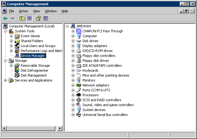
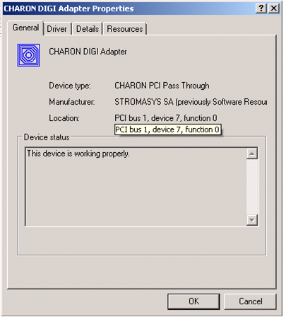
On the right panel select the desired physical EMULEX LP FibreChannel adapter under "CHARON PCI Pass Through":
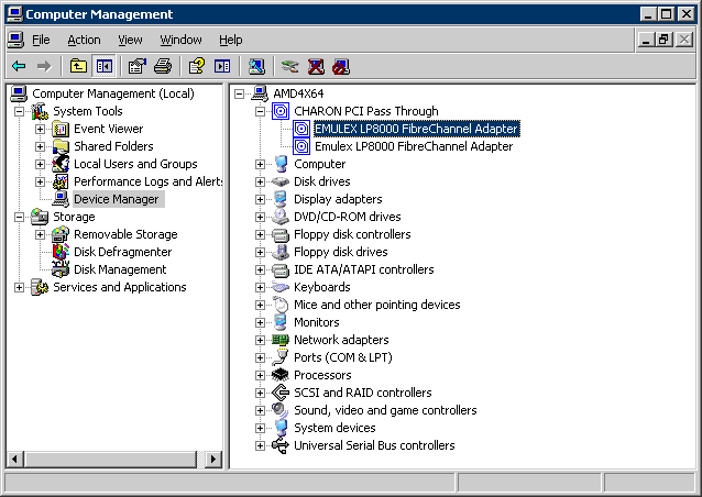
Open the properties sheet by double-clicking on the selected adapter:
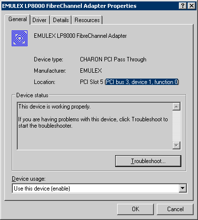
The “Location:” on the above picture gives X, Y, and Z for the "host_bus_location" parameter. For example:
|
![]() Non-US-EN installations of Windows may present “Location:” string in local language, but "host_bus_location" parameter requires English notation, so the words “PCI”, “bus”, “device”, and “function” must be specified in English.
Non-US-EN installations of Windows may present “Location:” string in local language, but "host_bus_location" parameter requires English notation, so the words “PCI”, “bus”, “device”, and “function” must be specified in English.
The following is the list of EMULEX LightPulse PCI/PCI-X/PCIe FC adapters supported by the CHARON-AXP PCI Pass Through driver and suitable for the emulation of a KGPSA-CA PCI FC adapter in CHARON PCI Pass Through mode:
| Supported | Not Supported | Not tested |
|---|---|---|
LP8000 | LPe1150 (FC2142SR, A8002A) | LPe11000 |
FDDI support via DEFPA PCI FDDI controller in "pass through" mode
Optionally it is possible to configure a DEFPA PCI FDDI controller in "pass through" mode, mapped to a physical DEFPA FDDI adapter installed on the host:
|
Pay attention to the proper placement of the emulated DEFPA adapter on the virtual HP Alpha PCI bus (it is controlled by "bus", "device", "function", "irq" and "irq_bus" parameters). Refer to this chapter of this Guide for more information.
The "host_bus_location" parameter addresses the host DEFPA FDDI adapter in the following way:
| Parameters | Description |
|---|---|
| "PCI bus X" | PCI bus number of the host DEFPA FDDI adapter |
| "device Y" | PCI bus device number of the host DEFPA FDDI adapter |
| "function Z" | The "function" parameter of the the host DEFPA FDDI adapter |
To establish the "pass through" mode do the following:
- Install the DEFPA FDDI adapter to some spare PCI slot of the host system. Note that PCIe and PCI-X are not supported by the DEFPA FDDI adapter.
- Boot a Windows operating system
- Install the DEFPA FDDI adapter driver from the following directory: "C:\Program Files\CHARON\Drivers\DEFPA_X.X.X.XXXXX" by choosing the "Install from a list or specific location (Advanced)" option and then selecting the "defpa_ppt_amd64.inf" file.
- Reboot the host
Now it is possible to collect the parameters for CHARON VM mapping to the DEFPA FDDI host adapter.
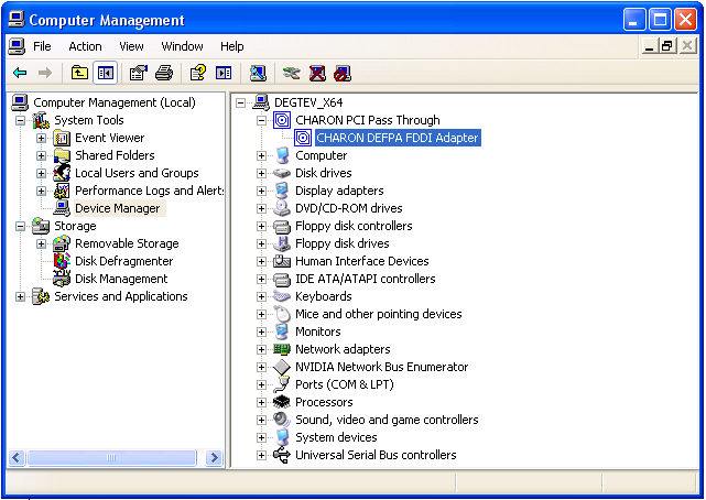
Open the “Computer Management” application and select “Device Manager”:
On the right panel select the installed DEFPA adapter:
Open the properties sheet by double-clicking on the selected adapter:
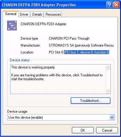
The “Location:” on the above picture gives X, Y, and Z for the "host_bus_location" parameter. For example:
|
![]() Non-US-EN installations of Windows may present “Location:” string in local language, but "host_bus_location" parameter requires English notation, so the words “PCI”, “bus”, “device”, and “function” must be specified in English.
Non-US-EN installations of Windows may present “Location:” string in local language, but "host_bus_location" parameter requires English notation, so the words “PCI”, “bus”, “device”, and “function” must be specified in English.
Serial lines support via emulated PBXDA-xx family PCI controllers
Optionally it is possible to configure the folIowing models of PBXDA-xx family controllers.
VIrtual PBXDA-xx
Syntax for loading PBXDA-xx family serial lines adapters:
|
Example:
load PBXDA_AC/DIGI TXA |
The adapter instance name ("TXA" in the example above) is used then for parametrization, for example:
set TXA line[2]="COM1:" |
The numbers in the square brackets represent line number on the virtual PBXDA adapter starting from 0.
Controller type | Maximum number of lines |
|---|---|
| PBXDA | 2 |
| PBXDA_BA | 4 |
| PBXDA_BB | 8 |
| PBXDA_AC | 16 |
It is possible to specify either physical port ("COM<n>") or an IP port for connecting the virtual PBXDA-xx to system resources. No other parameters are applicable in this type of emulation.
PBXDA-xx support in "pass through" mode
In "pass through" mode PBXDA-xx family controllers are mapped to specific models of the physical DIGI serial lines adapters installed on the CHARON VM host:
| DEC PBXDA-xx adapter | Name of the device to map to | Controller | Vendor ID | Device ID |
|---|---|---|---|---|
| PBXDA-BA | DIGI AccelePort 4r 920 | ASIC PCI | 114Fh | 0026h |
| PBXDA-BB | DIGI AccelePort 8r 920 | ASIC PCI | 114Fh | 0027h |
| PBXDA-AC | DIGI AccelePort Xem | ASIC PCI | 114Fh | 0004h |
| PBXDA-AC | DIGI AccelePort Xem | ASIC PCI | 114Fh | 0008h |
Below is an example of mapping to a physical DIGI adapter installed on the host:
|
Pay attention to the proper placement of the emulated PBXDA-xx adapter on the virtual HP Alpha PCI bus (it is controlled by "bus", "device", "function", "irq" and "irq_bus" parameters). Refer to this chapter of this Guide for more information.
The "host_bus_location" parameter addresses the host DIGI adapter in the following way:
| Parameters | Description |
|---|---|
| "bus X" | PCI bus number of the host DIGI adapter |
| "device Y" | PCI bus device number of the host DIGI adapter |
| "function Z" | The "function" parameter of the the host DIGI adapter |
To establish the "pass through" mode do the following:
- Install the DIGI adapter of the required type to some spare PCI/PCI-X/PCIe slot of the host system.
- Boot a Windows operating system
- Install the DIGI adapter driver from the following directory: "C:\Program Files\CHARON\Drivers\DIGI_X.X.X.XXXXX" by choosing "Install from a list or specific location (Advanced)" option and then selecting the "digi_ppt_amd64.inf" file.
- Reboot the host
Now it is possible to collect the parameters for CHARON VM mapping to the DIGI host adapter.
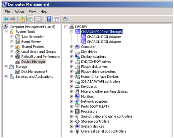
Open the “Computer Management” application and select “Device Manager”:
On the right panel select proper physical DIGI adapter:
Open te properties sheet by double-clicking on the selected adapter:
The “Location:” on the above picture gives X, Y, and Z for the "host_bus_location" parameter. For example:
|
![]() Non-US-EN installations of Windows may present “Location:” string in local language, but "host_bus_location" parameter requires English notation, so the words “PCI”, “bus”, “device”, and “function” must be specified in English.
Non-US-EN installations of Windows may present “Location:” string in local language, but "host_bus_location" parameter requires English notation, so the words “PCI”, “bus”, “device”, and “function” must be specified in English.
Auto boot
The CHARON VM can be configured to automatically boot an operating system at start up by specifying the default boot device and setting the 'auto_action' parameter to 'restart' from the console.
Example: dka0 is defined as the default boot device
|
Related content
© Stromasys, 1999-2024 - All the information is provided on the best effort basis, and might be changed anytime without notice. Information provided does not mean Stromasys commitment to any features described.